How a frame is madeElectric two-wheelers · Process imagery
MOPEDOEM · Back to production partners

One production line · Fifteen stages

From steel tubing,
to a complete frame.

Enter the workshop and follow the process. Scroll down to see the scene and manufacturing points at each stage.

AI-generated photographic-style illustration · Not an on-site photographic record

Frame manufacturing · Process imageryPHOTOGRAPHIC PROCESS STUDY · AI GENERATED

Fifteen stages, one complete process route.

Choose a stage to enter its chapter. Every image is an AI-generated photographic-style illustration; process parameters follow the actual work instructions.

Written process guide

Generic process illustrations, not evidence of a factory owned by our company. Actual work instructions and acceptance requirements must be confirmed for the order.

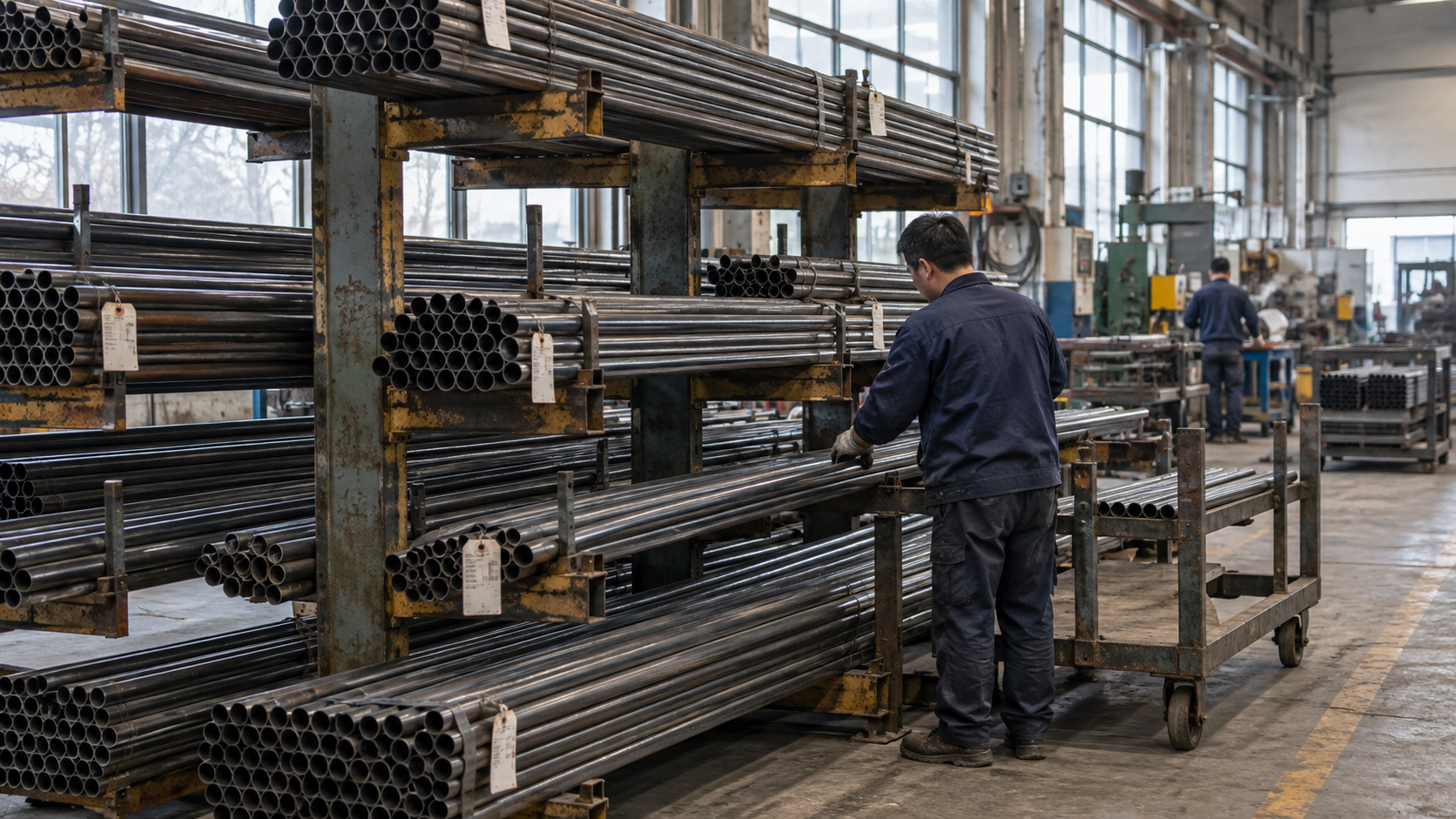
Steel tube stock area

Use separate racks by specification to prevent mix-ups.

  1. Check the work order and material identification, then select the specified stock.
  2. Lift the tube bundle out of the rack while supporting both ends.
  3. Check the issued quantity, then deliver the tubes to the cutting station’s loading rack.
Tube cutting

Clamp the tube once it reaches position and keep it supported throughout cutting.

  1. The infeed rollers move the tube into the locating area.
  2. The clamp closes to restrict axial and radial movement.
  3. The saw blade rotates and advances, then retracts to a safe position after cutting.
  4. The cut section drops into the receiving area; deburr its ends afterward.
CNC tube bending

Clamp and support the tube during bending, accounting for springback.

  1. Seat the straight tube against the stop and bending die.
  2. The clamp closes and the pressure die seats against the tube.
  3. The bending arm rotates, forming the tube around the die.
  4. Release the dies, remove the part and recheck it against a template.
Hole punching / Tapping

Clamp against the locating datum. Perform punching and tapping separately according to the work instructions.

  1. Place the tube in the lower die and locate it.
  2. The punch descends to form the hole, and scrap exits the die.
  3. The spindle rotates to tap the thread, then reverses to withdraw.
  4. Check the threads with the appropriate go/no-go gauge.
Robotic welding

Weld after clamping in the fixture. Follow the drawing for weld locations.

  1. Load the parts against the datums and secure the joints with clamping blocks.
  2. The robot approaches the weld start point and prepares to feed the wire.
  3. The torch strikes an arc and follows the seam to form the weld bead.
  4. Extinguish the arc and retract the torch before unclamping and unloading.
Weld inspection

Check weld appearance and critical joints.

  1. Inspect each weld along the joints.
  2. Move the gauge along the weld to check leg size and bead profile.
  3. Mark defects. Segregate nonconforming parts for rework.
Grinding and straightening

Remove excess material first, then straighten against the datums and remeasure.

  1. Bring the grinding wheel into contact with the weld area requiring finishing.
  2. Set the frame on the straightening fixture’s datum table.
  3. The ram presses downward within the allowed straightening travel.
  4. Retract the ram, then recheck critical dimensions.
Abrasive blasting

This stage precedes pretreatment. Transfer the part promptly after cleaning.

  1. Place the workpiece in the blast cabinet and close the work area.
  2. Sweep the blast nozzle across the surface. Abrasive flows only during cleaning.
  3. Dust extraction collects airborne dust, and abrasive is recovered.
  4. Remove residue and transfer the part to pretreatment.
Pretreatment

Transfer parts within the separate pretreatment section. Hanging starts after its exit.

  1. Degrease to remove oil from the surface.
  2. Rinse away residual solution to reduce contamination in subsequent tanks.
  3. Apply a conversion treatment to prepare the surface for coating.
  4. Check surface cleanliness at the final rinse.
  5. Hand the part over to the hanging station at the exit.
Cathodic electrocoating

Establish electrical contact through the hanger, deposit the coating in the bath, then rinse.

  1. Establish electrical contact at the hanging points and keep the frame stable.
  2. Lower the frame into the bath. The illustration shows the film depositing gradually.
  3. Lift the frame out of the bath and move it to the ultrafiltration rinse.
  4. Transfer the coated frame to a separate bake section.
Electrocoat baking

This section bakes the electrocoat film separately from the cure after powder coating.

  1. Rinse away loose paint and residual solution.
  2. Allow the part to drain to minimize liquid carryover into the oven.
  3. Bake according to the electrocoat requirements.
  4. After cooling, transfer the frame to the powder coating booth.
Electrostatic powder coating

Reciprocate the spray guns on both sides to avoid missed areas and excessive buildup.

  1. The hanger carries the frame into the spray booth.
  2. The guns scan up and down on both sides, illustrating powder deposition.
  3. Collect overspray in the recovery filtration section.
Coating cure

Heat-cure according to the coating requirements, then move the frame to cooling.

  1. The frame enters the curing tunnel at a steady speed.
  2. Heat according to the coating's cure profile so the powder flows out and cures.
  3. After exiting the oven, move into the separate cooling and unloading section.
Cooling / Unhanging

Unload after cooling. Empty hangers return along the rear side.

  1. Fans assist cooling while frames remain spaced apart.
  2. Inspect the finish and avoid impacts during transfer.
  3. Lower the frame onto the receiving rollers while the empty hanger continues.
  4. Transfer the frame to final inspection; empty hangers return along the rear side.
Final inspection and storage

Inspect first, then scan, pack and put into storage.

  1. Check against the drawing, inspect appearance and verify critical items.
  2. Scan to link the frame identifier to its batch.
  3. Place it in the designated rack location and protect the finish from impacts.

    Images are AI-generated process illustrations, not actual factory photographs. Clicking a step displays an explanation; it does not mean equipment in the image is playing the corresponding action.