How a motor controller is madeElectric two-wheelers · Motor controller
MOPEDOEM · Back to production partners

Four main stages · General process illustration

From power circuitry,
to coordinated motor drive.

Enter the workshop and follow the process. Scroll down to see the scene and manufacturing points at each stage.

General manufacturing illustration · Not a record from a partner supplier’s site

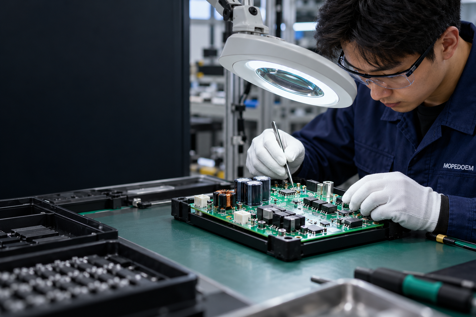
AI-generated photographic-style illustration · Not an on-site photographic record

Motor controller · Process imageryPHOTOGRAPHIC PROCESS STUDY · AI GENERATED

Four main stages. Expand each one to review the process details.

Choose a stage to enter its chapter. Every image is an AI-generated photographic-style illustration; process parameters follow the actual work instructions.

Written process guide

Generic process illustrations, not evidence of a factory owned by our company. Actual work instructions and acceptance requirements must be confirmed for the order.

Circuit board and electronics assembly

Check components and circuit boards against the approved design, and complete the applicable assembly and quality checks.

  1. Check power devices, control circuits and board batches. Distinguish rated operating conditions from peak conditions.
  2. Install components using the prescribed electrostatic discharge controls and assembly procedures. Check polarity and orientation.
  3. Check solder joints, connections and required circuit items against the inspection documents. Do not provide unverified universal electrical limits.
Power device and thermal assembly

Install the power devices, insulation and heat transfer structures according to the design. Check their fit with the heat-dissipating housing.

  1. Check insulation, thermal interface materials and the housing structure. Do not confuse heat transfer with electrical insulation.
  2. Secure devices and heat dissipation structures according to the design. Do not prescribe universal thermal interface thicknesses or tightening torques.
  3. Check clearances, wiring harness strain and connector protection. Verify actual temperature rise under the specified operating conditions.
Configuration and controlled bench verification

Check revisions and compatibility at a controlled station, then verify functions against the approved plan.

  1. Check the motor, sensors, supply range and communications configuration. Qualified personnel must follow the prescribed procedures.
  2. Perform applicable tests under approved conditions and with the required safeguards. The pictured equipment does not demonstrate actual testing capabilities.
  3. Record functional and specified protection test results as planned. Do not substitute generic values for validation on the actual vehicle.
Housing, sealing and final handover

Complete housing, wiring harness and protective work according to the actual design. Pack after final inspection.

  1. Select sealing or other protective processes for the specific design. Methods such as potting are not suitable for every controller.
  2. Follow the specified sequence for checks before and after protective treatment. Recheck labels and configuration, and do not claim an unverified protection rating.
  3. Protect terminals and wiring harnesses. Check the batch, interface documentation and packing list, and hand over according to the order.

    Images are AI-generated process illustrations, not actual factory photographs. Clicking a step displays an explanation; it does not mean equipment in the image is playing the corresponding action.