Choose a stage to enter its chapter. Every image is an AI-generated photographic-style illustration; process parameters follow the actual work instructions.
Written process guide
Generic process illustrations, not evidence of a factory owned by our company. Actual work instructions and acceptance requirements must be confirmed for the order.
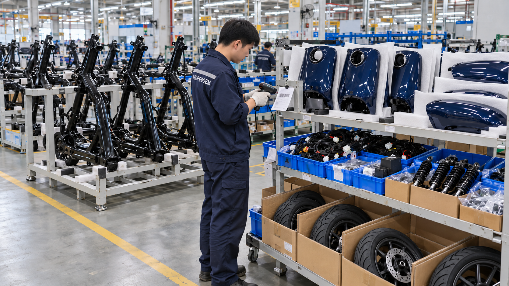
Incoming inspection / Parts kitting
Kit parts by model, colour and configuration, bringing together approved materials from the frame and panel-painting suppliers.
- Check the work order, BOM revision and matching frame, hub motor, battery, controller and body-panel configuration.
- Confirm incoming release, identification and appearance. Panels enter final assembly in their finished paint colour after coating at the painting supplier.
- Sort by vehicle sequence and station. Segregate missing, mixed and nonconforming parts and retain batch traceability.
Frame loading / Positioning
Place the frame on the assembly carrier, protect its finish and link the vehicle to the production order.
- Recheck the frame identification and work order; establish or verify the link between the vehicle and assembly record.
- Place the frame on the fixture's load-bearing points. Do not carry weight through body-panel mounting positions or wiring brackets.
- Confirm stable clamping and protection at contact points to avoid damaging the coating and mounting datums.
Steering bearings / Front fork
Fit bearings, seals and the front fork for the model, checking smooth steering and clearance.
- Check the sequence of bearings, washers and seals; prepare contact surfaces and lubrication according to the work instructions.
- Support the fork steadily and fit the steering stem correctly into the frame head tube, avoiding damage to bearings and threads.
- Set preload and lock the assembly according to the model's instructions; recheck turning resistance, clearance and stops.
Rear swingarm / Rear suspension
Support the rear swingarm before fitting bushes, the pivot shaft and shock absorbers to avoid uneven assembly loads.
- Check that the swingarm, bushes, washers and connectors match the model; support the assembly position with a fixture.
- Fit the pivot shaft and associated parts in the specified orientation; check for omissions, misalignment and pinching.
- Assemble the upper and lower shock mounts; tighten in the specified loaded condition and sequence, and record the operation.
Rear wheel / Hub motor
This page illustrates a rear hub-motor model. Confirm axle-end positioning, anti-rotation parts and motor-cable protection together.
- Use a lifting device to position the motor rear wheel in the swingarm. Do not lift the wheel by pulling the motor cable.
- Check axle-end orientation, locating washers, anti-rotation structures and brake fit according to the model requirements.
- Tighten and record according to the work instructions. Route the motor cable through sleeves and fixing points, leaving suspension movement allowance.
Front wheel / Brake assembly
This page illustrates disc brakes. Install the axle, spacers, disc and caliper according to the model.
- Check the wheel, tyre direction and axle bushes. Support the wheel and align it with the fork mounting position.
- Install the caliper and associated fasteners as specified; protect the brake disc and friction pads from oil and impact.
- Tighten in sequence and record. Check wheel-end clearance, rotation and brake interference; hydraulic lines are connected and adjusted later.
Handlebar / Controls / Instruments
Fit the handlebar, brake levers, throttle, switches and instruments. Check clearances through the full steering travel.
- Set handlebar direction and clamp position to the model's datums, then tighten in the specified sequence.
- Install the throttle, brake levers and switches. Confirm moving-part return, clearance and fastening condition.
- Fit the instruments and bracket and provisionally route cables and hoses. Nothing should pull tight or collide at full left or right lock.
Main wiring harness / Controller
Keep traction power isolated. Route to the wiring diagram and confirm connector locks, sealing and movement allowance.
- Check the harness, controller, converter and model revision. Keep traction power isolated and follow electrical work procedures.
- Mount the controller and associated brackets. Route through the fixing points, avoiding sharp edges, heat sources and moving interference zones.
- Match connectors and confirm locks, seals and sleeves. Recheck slack throughout steering and suspension travel.
Brake connections / Static adjustment
The hydraulic disc brakes illustrated here are connected, bled and inspected according to the instructions. Powered running is not performed at this stage.
- Confirm hose specification, fittings, anti-chafe fixing points and allowances for steering and suspension movement.
- For hydraulic systems, use the model-specified fluid and dedicated bleeding equipment. Check lever travel, return and leakage; use the relevant procedure for other brake systems.
- Recheck wheel rotation, brake drag, suspension movement and previous critical-fastener records. Proceed only after acceptance.
Battery system installation
Install the matching complete battery pack, confirming protection and retention. Maintain the specified isolation until the power-on stage.
- Check battery model, identification, configuration compatibility and release status. Inspect the casing, connectors and transport damage.
- Use suitable handling or lifting equipment to place it in the bracket. Confirm support, anti-loosening and locking structures.
- Follow electrical assembly procedures to check connectors, polarity identification, cable fixation and protection. Maintain specified isolation before controlled power-on; this illustration does not replace live-work procedures.
Body panels / Lighting assembly
The panels are finished products from the preceding painting process. Natural-colour ABS is shown only when illustrating unpainted substrates.
- Check front and rear lights, brackets and matching wiring. Confirm connectors, waterproof sleeves and fastening according to the instructions.
- Align clips and mounting points in sequence. Fit front panels, side covers and footboard parts while protecting painted surfaces.
- Inspect each clip, screw, harness pinch point and fit gap. Do not force plastic panels to compensate for assembly errors.
Seat bucket / Seat / Accessories
Complete the model's seat bucket, seat, latch, mirrors and footrests, retaining the required testing interfaces.
- Install the seat bucket and seat according to the model structure. Protect the battery, harness and latch, and confirm opening clearance.
- Fit mirrors, passenger footrests and ordered accessories. Check the seat lock, stands and moving parts.
- Verify assembly completeness, supplied configuration and testing interfaces. Remove tools and foreign material before commissioning.
Controlled power-on / Functional commissioning
Power on under control at the specified inspection station. Check displays, lights, horn and model-specific interlocks.
- Recheck mechanical assembly, traction connections and protection. Energize according to the station procedure, keeping the vehicle securely restrained.
- Use the model-appropriate diagnostic tool to verify version, configuration, fault status and specified system parameters.
- Check displays, switches, lights, horn and specified brake or stand interlocks item by item. Record, isolate and recheck abnormalities; do not pass faults to the next stage.
Vehicle performance / End-of-line testing
Verify drive, braking and other items on suitable test benches and controlled stations. Items, scope and limits follow the model inspection plan.
- Confirm equipment status, model program, wheel positioning, restraints and protection. Enter the testing station according to the operating procedure.
- Check drive, braking, unusual noise and operating condition using validated test items. Record the results; instruments depicted in images do not replace actual measurement.
- Schedule lighting checks, specified electrical tests and any required sampled rain tests at the appropriate stations. Isolate abnormalities, correct them and retest.
Final appearance inspection / Vehicle release
Review appearance, assembly, testing and traceability records. Release only after all items are closed.
- Inspect paint finish, colour, gaps, lighting, seat and accessories under the specified light source and inspection conditions.
- Check vehicle identification, configuration, critical-fastening and test records. Confirm that no process item is missing and no abnormality remains open.
- Segregate nonconforming vehicles, resolve issues and reinspect as required. Proceed to packing only when the records meet release requirements.
Packing / Warehousing / Dispatch
Protect paint and fragile parts according to the order's packing plan. Check supplied materials, labels and dispatch information.
- Check release status, model configuration, keys and accompanying documents. Complete shutdown, transport-state and battery arrangements as specified.
- Protect appearance, lighting and controls according to the packing design. Confirm the base, securing points and outer packaging; protect and identify removed parts separately.
- Record carton numbers, vehicle associations and warehouse locations. Dispatch and hand over according to the order and applicable transport requirements.